Leave A Message
If you are interested in our products and want to know more details,please leave a message here,we will reply you as soon as we can.

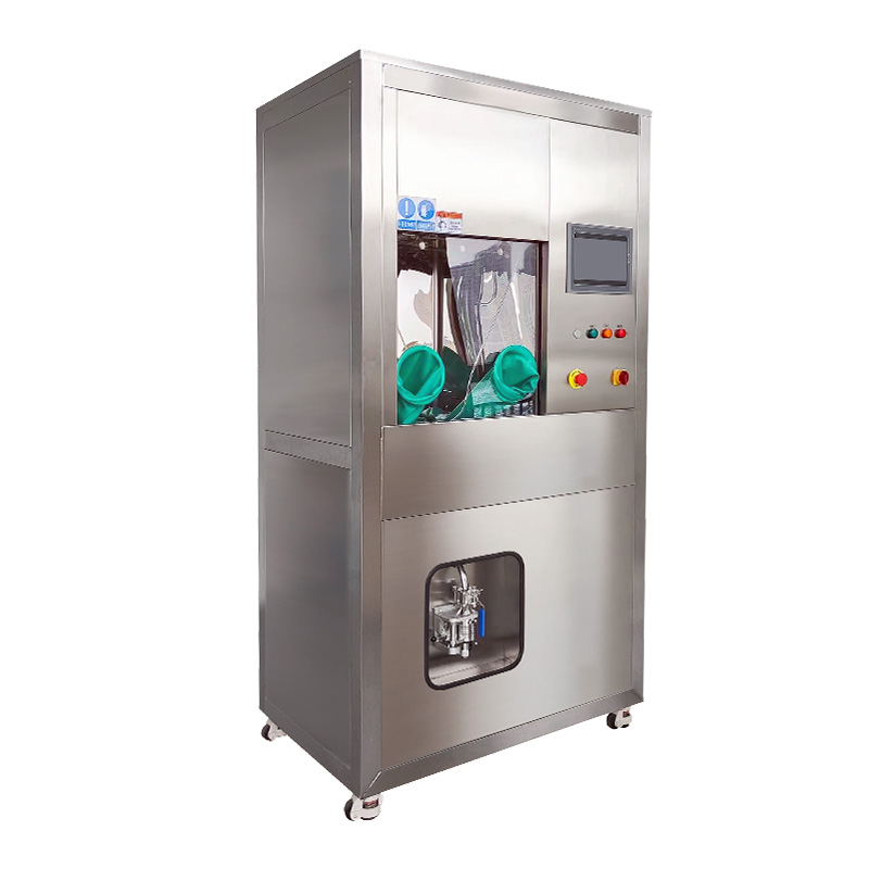
CLS-S Double Chamber VDA 19.1 Technical Cleanliness Test Equipment
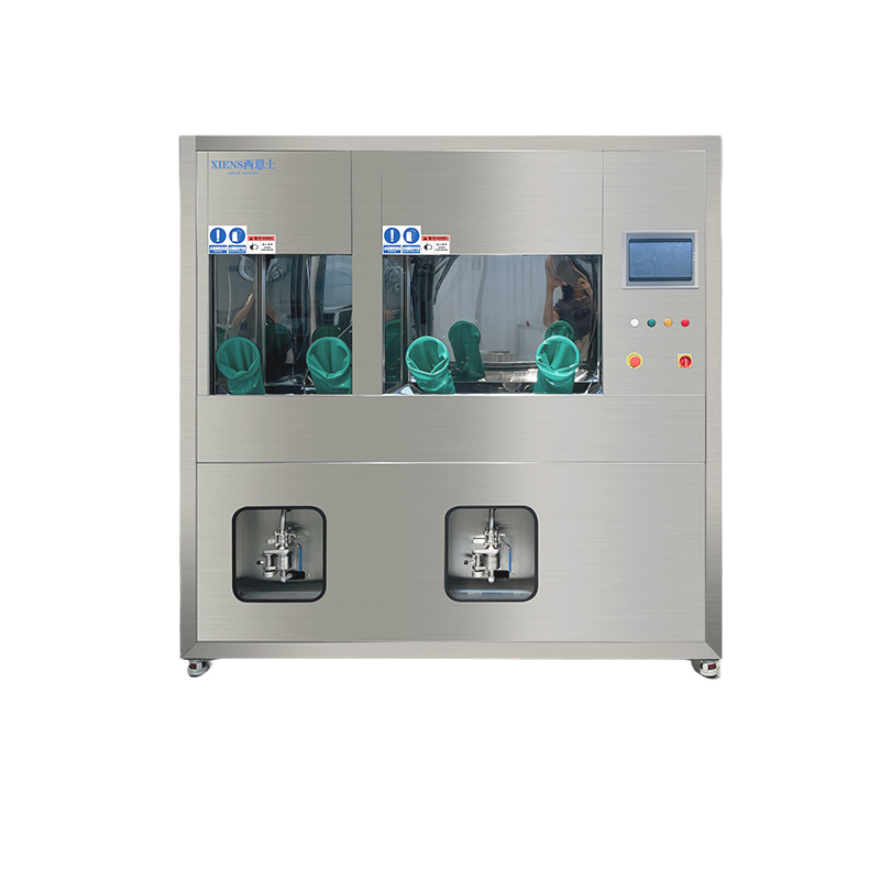
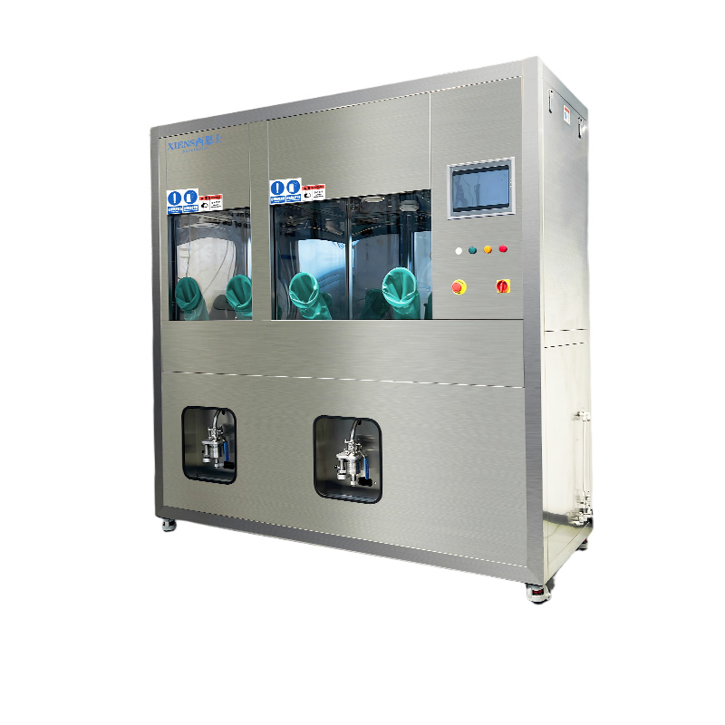
CLS-S double chamber cleanliness cabinet with separate rinsing conical trough chamber and ultrasonic conical trough chamber, integrates pressure-rinsing cleaning, spray cleaning, side wall spray self-cleaning, ultrasonic cleaning, membrane sample preparation (particle extraction), online filtration and recovery of cleaning agents, and circulating fine filtration into one.
The separate extraction chamber system is the optimal solution that divide the different products into two independent cabins for cleanliness testing; So as to avoid the mutual pollution caused by different extraction methods of different products in a cabin, in this way to make sure all test following up the ISO 16232 and VDA19.1 analysis processes.
| Description |
Model
-CLS-S
Purpose of the device
-Used for cleaning and extracting particles from components.
Equipment principle
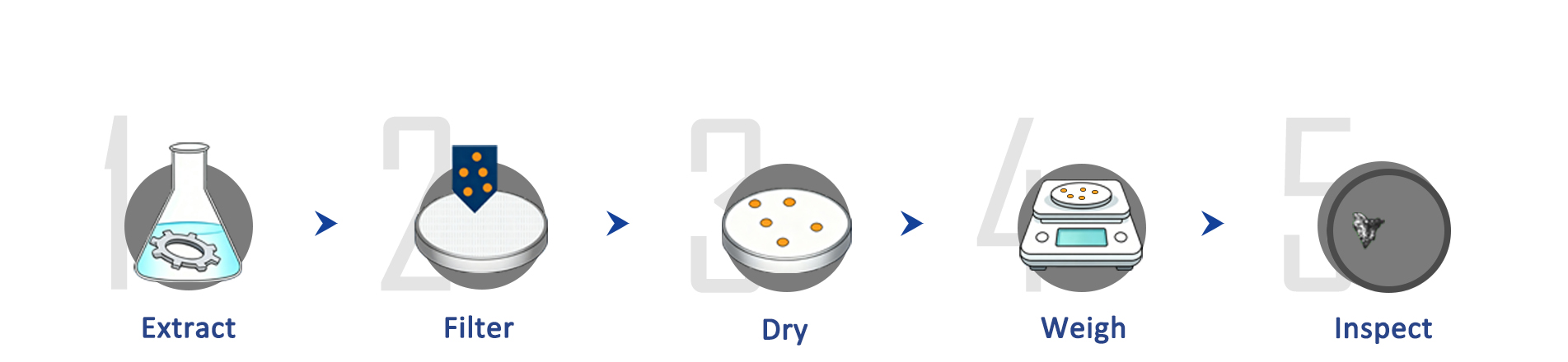
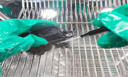
-Wet extraction: Using a specified liquid medium, flushing the surface of components with a standard nozzle within a set pressure range to separate solid particles from the components, which are then collected on the detection filter membrane.
-Ultrasonic extraction:By utilizing the cavitation effect of ultrasonic waves in liquids, bubbles are generated in the liquid. These bubbles come into contact with the surface of the product and collapse, thereby disrupting insoluble attached particulate contaminants, causing them to disperse in the solution, and ultimately achieving the effect of cleaning particulate contaminants from the surface of the parts.
Equipment advantages
-The equipment has real time display of equipment working status, continuously adjustable parameters.
-After cleaning the parts, a filter membrane sample can be obtained directly to reduce the retention time of particulate contamination in the cleaning agent; which standardizes the cleanliness testing control process and improves testing efficiency.
-The operating space for cleaning parts is relatively independent, with a built-in air laminar flow system to purify the cleaning operating environment, effectively isolate the cleaning area and external environment, and build a clean operating platform for cleaning and testing.
-Reference standards for equipment design and operation methods:VDA19.1 2015 edition, ISO16232 2018 edition, and customer defined standards.
Structural overview
|
1 |
Separate pressure-rinsing cleaning chamber and ultrasonic chamber |
5 |
Swivel wheel |
|
2 |
Protective glove |
6 |
Operating panel |
|
3 |
PLC programmable controller |
7 |
Foot switch |
|
4 |
Distribution box |
8 |
Three-stage filter membrane sample preparation |
| Ultrasonic automatic cleaning |
Ultrasonic vibration cleaning utilizes the direct and indirect effects of ultrasonic waves' cavitation, acceleration, and rectilinear flow in liquids on the liquid and contaminants. It generates pressure of 10¹²-10¹³ Pa and local temperature adjustment around the bubbles, which destroys the adhesion of insoluble particulate contaminants, causing them to disperse in the solution. Ultimately, it achieves the effect of cleaning particulate contaminants from the surface of components. The cleaning effect is superior to pressure cleaning, with better cleaning uniformity. This function is integrated into the equipment, enabling fully automatic ultrasonic cleaning and a higher degree of automation in cleaning and detection.
| Pressure/flow rate flushing |
The components are inspected with a spray gun set at a certain pressure or flow rate, angle, and then extracted and collected residual particles. The spray cleaning pressure (National standard) or flow rate (European standard) can be set, and the operation can be carried out in a quantitative or timed manner with a set flow rate. The specific requirements are based on the cleanliness operation specifications of different components.
| Technical parameter |
|
CLS-S Double Chamber VDA 19.1 Technical Cleanliness Test Equipment |
||
|
Material |
The equipment frame and appearance are all made of 304 stainless steel. |
|
|
Function |
Pressure-rinsing cleaning, ultrasonic cleaning, circulation cleaning, single cleaning, liquid addition, liquid drainage, manual testing, parameter setting, etc. |
|
|
Overall dimensions |
1750*800*2100mm(Including casters 2100mm) |
|
|
Pressure-rinsing chamber |
Analysis area |
600 * 600 * 800mm (L*W*H) |
|
Compatible Product |
Length≤400mm |
|
|
Control system |
PLC control, software with flushing option and programmable flushing volume. |
|
|
Maximum loading capacity |
≥30 Kg(Uniform loading, non-point loading) |
|
|
Working pressure |
0.1-0.45Mpa (customizable) |
|
|
Flow rate |
1L/min-5.0L/min (customizable) |
|
|
Ultrasonic |
Analysis area |
600*600*800mm(L*W*H) |
|
Ultrasonic power |
0-600W(adjustable) |
|
|
Power density |
According to VDA19.1 10W/L(adjustable) |
|
|
Frequency |
40KHZ |
|
|
Storage and filtration |
Testing membrane size |
Φ47 – 50mm |
|
Tank capacity |
30L (customizable) |
|
|
Filtration system |
1μm、0.2μm filter (absolute filtration) |
|
|
Membrane system |
3-stage cascade filtration system |
|
|
Rinsing nozzle |
Φ2.5 mm column nozzle |
|
|
Blank value |
Comply with ISO16232-3 standard, the maximum particle size must be less than 50% of the allowable particle size on the part/product, and the particle quantity within the blank value shall not exceed 10% of the cleanliness level required for the component. Equipment capacity: Pollutant weight 0.3mg, Metal particles ≤ 100um(particles in a Class 10,000 cleanroom≤ 50um) |
|
|
Cleaning medium |
Recommended hydrocarbon solvents (AP760/ISO Sparl) |
|
|
Operation protective gloves |
Length 360mm, nitrile rubber |
|
|
Chamber door |
Electric lifting |
|
|
Alarm |
Liquid level alarm for storage tank, filter element expiration prompt alarm, mis-operation/fault alarm; provide solution |
|
|
HEPA filter |
99,995% efficiency for particles bigger than 0.3 µm |
|
|
Power |
AC220V,50Hz; Rated power: 900W |
|
|
Work noise |
Less than 70db |
|
|
Equipment activation |
≥98% |
|
|
Equipment failure rate |
≤2% |
|
|
Totally weight |
About 450KG |
|
| Technical Cleanliness Inspection Standards |
|
Standards |
Mainly used for |
|
ISO 11218:1993 |
Aerospace - Cleanliness classification for hydraulic fluids |
|
ISO 12345:2013 |
Diesel engines - Cleanliness assessment of fuel injection equipment |
|
ISO 14952:2003 |
Space systems - Surface cleanliness of fluid systems |
|
ISO 16232-10:2007 |
Road vehicles - Cleanliness of components of fluid circuits |
|
ISO 4406:1999 |
Hydraulic fluid power - Fluids - Method for coding the level of contamination by solid particles |
|
ISO 4407:1991 |
Hydraulic fluid power - Fluid contamination - Determination of particulate contamination by the counting method using a microscope |
|
NAS 1638:2011 |
Cleanliness requirements of parts used in hydraulic systems |
|
NF E 48-651:1986 |
Transmissions Hydrauliques - Fluides - Determination De La Pollution Particulaire Par La Methode De Comptage Au Microscope |
|
NF E 48-655:1989 |
Hydraulic fluid power - Fluids - Particulate contamination - Expression of results |
|
NF ISO 21018-1:2008 |
Hydraulic fluid power - Monitoring the level of particulate contamination of the fluid |
|
SAE AS 4059:2011 |
Aerospace Fluid Power - Cleanliness Classification for Hydraulic Fluids |
|
VDA 19.1:2015 |
Fluid circuits in automotive-Inspection of Technical Cleanliness |
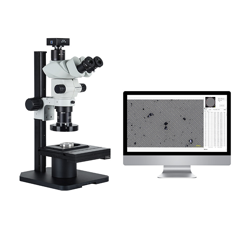
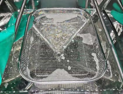
| Internal Structure |
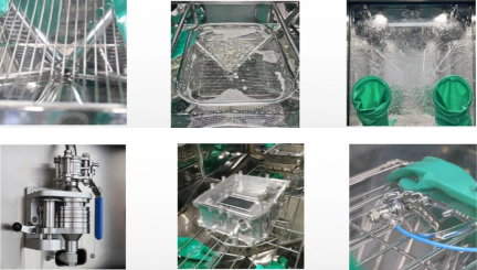
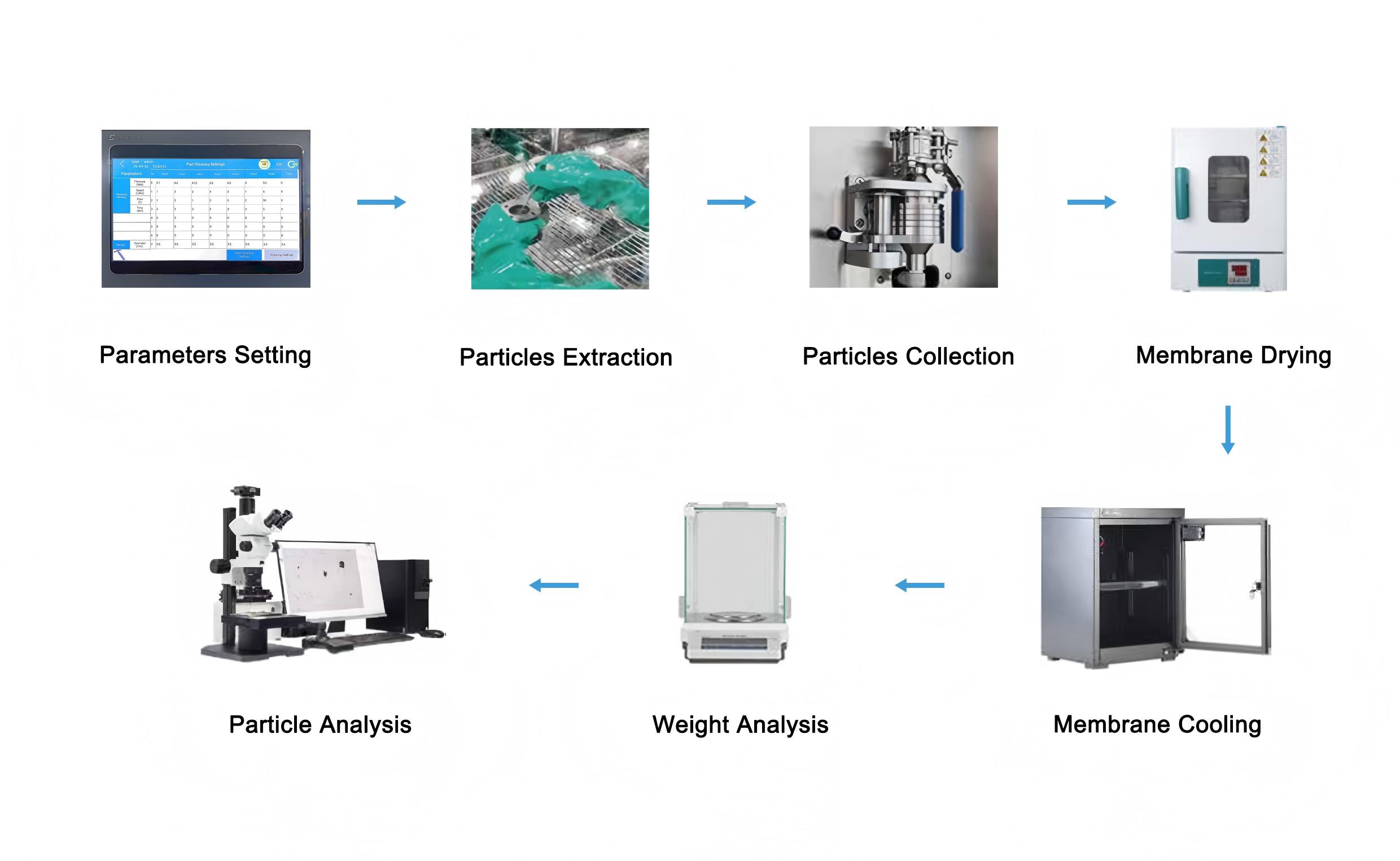
| Technical Cleanliness Testing Process |
CLS300U ultrasonic baths are especially suitable for extracting contamination from small components with complex structures, micro-holes / blind holes / narrow slits, and high precision requirements that are difficult to handle individually because they can be sampled in bulk. By directly or indirectly applying ultrasonic waves to liquids and particles contaminants, the adhesion of insoluble particles contaminants is disrupted, causing them to disperse in the liquid to collect particles on the filter membrane. CLS300U ultrasonic cleanliness cabinet with 300mm*150mm(L*D) ultrasonic bowl for low blank value around 50μm, CLS300U with pressure-rinsing, spray cleaning, ultrasonic cleaning, membrane sample preparation (particle extraction).
Read More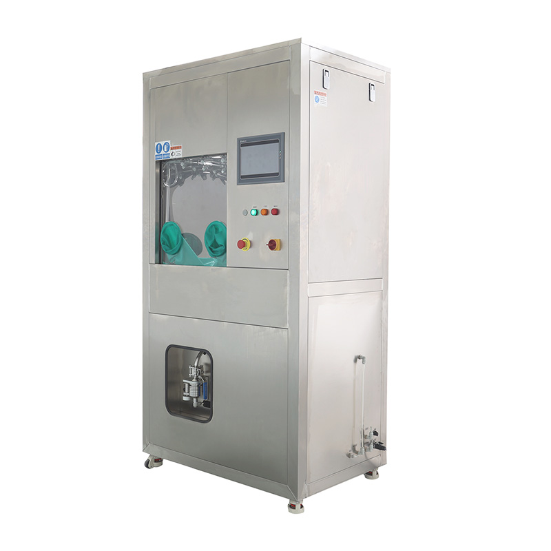
CLS400U ultrasonic baths are especially suitable for extracting contamination from small components such as fluid circuits, precision machinery, electronics and medical devices with high precision requirements that are difficult to handle individually because they can be sampled in bulk. By directly or indirectly applying ultrasonic waves to liquids and particles contaminants, the adhesion of insoluble particles contaminants is disrupted, causing them to disperse in the liquid to collect particles on the filter membrane. CLS400U ultrasonic cleanliness cabinet with 400mm*200mm(L*D) ultrasonic tank integrates pressure-rinsing, spray cleaning, ultrasonic cleaning, membrane sample preparation (particle extraction).
Read More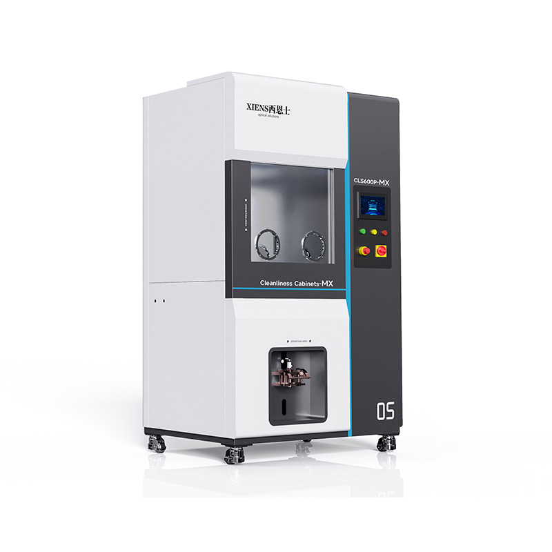
CLS600P-MX technical cleanliness extraction system complied with ISO 16232 and VDA 19.1 standards is the most commonly used extraction method, which covers a large portion of the requirements for particle extraction from components which require low blank value. CLS600P-MX technical cleanliness cabinet with 600 * 600 * 800mm (L*W*H) ceramic coating operation chamber for small to midsized components, the technical cleanliness cabinet with function as below: pressure-rinsing cleaning, spray cleaning, side wall spray self-cleaning, membrane sample preparation (particle extraction), online filtration and recovery of cleaning agents, and circulating fine filtration.
Read More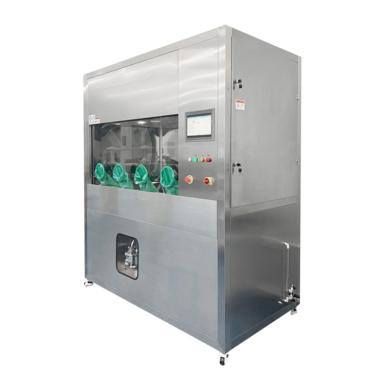
CLS900P extraction systems for technical cleanliness complied with ISO 16232 and VDA 19.1 standards is the most commonly used extraction method, which covers a large portion of the requirements for particle extraction from components. CLS900P technical cleanliness cabinet with 900 * 700 * 800mm (L*W*H) operation chamber for midsized to large components, we customized the pressure-rinsing cleaning, spray cleaning, side wall spray self-cleaning, membrane sample preparation, online filtration and recovery of cleaning agents, and circulating fine filtration functions into one cleanliness cabinet to make particle extraction work easy.
Read More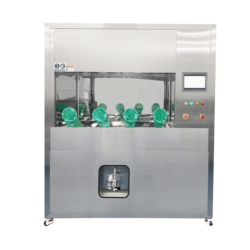
CLS1100P component cleanliness & flushing equipment complied with ISO 16232 and VDA 19.1 standards is the most commonly used extraction ways, which covers a large portion of the requirements for particle extraction from components. CLS1100P technical cleanliness cabinet with 1100 * 700 * 800mm (L*W*H) operation chamber for large components, integrates pressure-rinsing cleaning, spray cleaning, side wall spray self-cleaning, membrane sample preparation, online filtration and recovery of cleaning agents, and circulating fine filtration into one to make ISO 16232 and VDA19.1 analysis processes easy.
Read More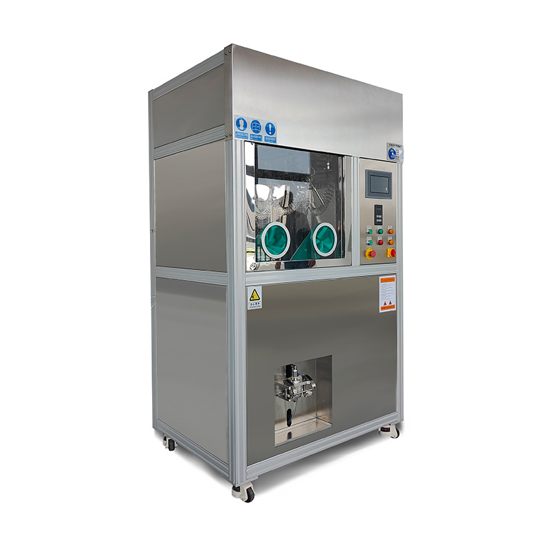
CLS-A dry extraction system enables non-destructive sampling of electronic components and the gentle separation of particles from the component using filtered air without damaging it. Then using a spray to clean the cabinet wall to collect particles on membrane. CLS-A air jet extraction cleanliness cabinet with air blow integrates pressure-rinsing cleaning, spray cleaning, air blow, side wall spray self-cleaning, membrane sample preparation (particle extraction), online filtration and recovery of cleaning agents, and circulating fine filtration into one to meet the inspection of VDA19.1&ISO16232 technical cleanliness.
Read More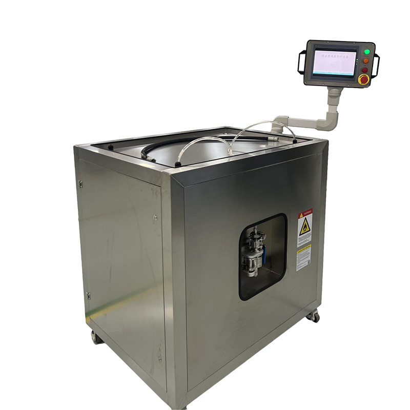
CLS-IR internal rinsing extraction system impurity extraction of the inner surfaces of a sample that can be flushed through. CLS-IR internal rinsing cleanliness cabinet integrates spray cleaning, internal rinsing, membrane sample preparation (particle extraction). The CLS-IR internal rinsing extraction system is suitable for components like passive components such as tubing, lines, channels, filters and heat exchangers active components needing to be actuated for the throughflow process, such as valves and injectors, or even driven, such as pumps.
Read More
CLS-S double chamber cleanliness cabinet with separate rinsing conical trough chamber and ultrasonic conical trough chamber, integrates pressure-rinsing cleaning, spray cleaning, side wall spray self-cleaning, ultrasonic cleaning, membrane sample preparation (particle extraction), online filtration and recovery of cleaning agents, and circulating fine filtration into one. The separate extraction chamber system is the optimal solution that divide the different products into two independent cabins for cleanliness testing; So as to avoid the mutual pollution caused by different extraction methods of different products in a cabin, in this way to make sure all test following up the ISO 16232 and VDA19.1 analysis processes.
Read More


 IPv6 network supported
Leave A Message
Scan to Wechat :

Scan to Whatsapp :

 English
 Français
 Русский
 Español
 Português
 عربي
عربي Get A Quote