What Types of Contaminants Does Technical Cleanliness Primarily Control?
Content Summary
Technical Cleanliness, typically evaluated in accordance with standards such as ISO 16232 and VDA 19.1, is designed to quantify and control microscopic foreign matter that can affect the performance, reliability, and service life of precision components.
In practical cleanliness testing, contaminants can generally be categorized according to their physical form and material properties, including metallic hard particles, non-metallic hard particles, non-metallic soft particles, fibers, and liquid or film-like residues. These contaminants can originate from machining and manufacturing processes, production environments, handling and packaging, as well as component assembly and early-stage operation.
This article provides a systematic overview of the major contaminant types controlled by technical cleanliness requirements, their typical sources, potential failure mechanisms, and the key evaluation parameters used in industrial cleanliness analysis. These parameters include maximum particle size (Lmax), material classification, Component Cleanliness Code (CCC), and gravimetric contamination load.
In modern industrial manufacturing, components are becoming increasingly precise, compact, and highly integrated. As a result, even microscopic foreign particles remaining on component surfaces or inside internal channels can become potential sources of system malfunction.
Technical Cleanliness, commonly assessed according to ISO 16232 (Road vehicles — Cleanliness of components and systems) and VDA 19.1 (Inspection of Technical Cleanliness — Automotive Industry), provides a standardized approach for extracting, analyzing, classifying, and quantifying these contaminants.
So, what types of contaminants are primarily controlled in technical cleanliness inspections?
The answer can be examined from four perspectives: contaminant morphology and physical properties, sources and process stages, potential damage mechanisms, and key industrial evaluation parameters.
1. Major Contaminant Types by Morphology and Physical Properties
During cleanliness extraction and microscopic analysis, laboratories typically use optical microscopy and, when necessary, scanning electron microscopy with energy-dispersive X-ray spectroscopy (SEM-EDS) to characterize and classify extracted particles.
From the perspective of physical form and material properties, the major contaminant categories include the following.
1.1 Metallic Hard Particles
Metallic particles are among the most critical contaminants in technical cleanliness control, particularly when they are large, sharp, or electrically conductive.
Typical examples include:
Ferromagnetic metals: cast-iron machining chips, carbon-steel wear debris, hardened-steel fragments, and particles generated from threaded components.
Non-ferrous or non-magnetic metals: aluminum-alloy burrs, brass chips, copper particles, stainless-steel fragments, and welding residues.
Physical characteristics:
Metallic particles typically exhibit a metallic appearance and strong light reflection under reflected illumination. Many machining chips and fragments have sharp edges and are relatively hard and non-compressible.
Why must they be controlled?
Metallic particles can become trapped in precision clearances and cause scratching, scoring, abrasive wear, or mechanical seizure in components such as hydraulic valves, bearings, shafts, and powertrain components.
In high-voltage electrical systems, including new-energy vehicle battery systems and electronic control units (ECUs), conductive metallic particles can also create electrical leakage, short circuits, or other insulation-related risks, depending on their size, location, and operating conditions.
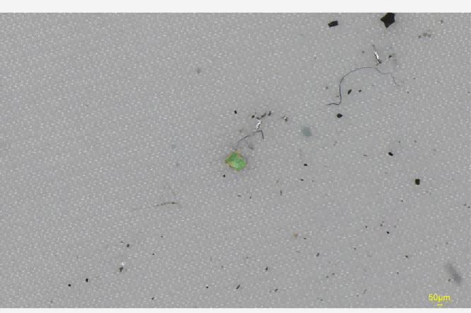
1.2 Non-Metallic Hard Particles
Non-metallic hard particles are generally inorganic contaminants. Some have relatively high hardness and can produce significant abrasive effects when introduced into precision mechanical or fluid systems.
Typical examples include:
Quartz sand from casting processes
Glass beads or blasting media
Alumina or other abrasive residues from grinding
Ceramic particles
Environmental dust and mineral particles
Physical characteristics:
Unlike metallic particles, these contaminants generally do not exhibit metallic luster. Under optical microscopy, they may appear as translucent, transparent, or dark irregular particles, depending on their composition and morphology.
Some mineral-based particles can have hardness significantly higher than the surrounding component material.
Why must they be controlled?
Hard non-metallic particles can cause abrasive wear when they enter moving or fluid-carrying systems. During fluid circulation, they may damage pumps, sealing surfaces, precision valves, and internal channels, potentially accelerating wear and affecting sealing performance.
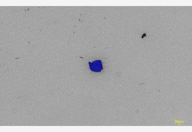
1.3 Non-Metallic Soft Particles and Polymer Contaminants
Non-metallic soft contaminants are generally associated with polymers, elastomers, coatings, adhesives, or other organic materials used during manufacturing and assembly.
Typical examples include:
Rubber particles from sealing components
Plastic particles
Coating or paint flakes
Cured adhesive or sealant residues
Agglomerated release-agent residues
Physical characteristics:
These contaminants generally lack metallic luster and have irregular shapes. Compared with metallic and mineral particles, many polymeric contaminants are relatively soft and may deform when subjected to mechanical pressure.
Why must they be controlled?
Although they are generally less abrasive than hard particles, soft contaminants can accumulate in small fluid passages, orifices, fuel-injection components, valves, and fine filters.
Accumulation may restrict flow, interfere with valve operation, or cause partial or complete blockage of critical passages.
1.4 Fiber Contaminants
Fibers require special attention because their elongated geometry and high aspect ratio distinguish them from conventional particulate contamination.
Typical examples include:
Natural fibers:
Cotton or linen fibers from cleaning cloths
Fibers from paper packaging
Wood-derived fibers or dust from pallets
Synthetic fibers:
Fibers shed from protective clothing
Nylon or polymer brush bristles
Nonwoven fabric fibers
Fibers generated by wear of lifting straps
Fiber classification is based primarily on geometric characteristics, including particle length, width, and aspect ratio. Specific classification limits should be determined according to the applicable version and evaluation method of ISO 16232, VDA 19.1, or the customer's cleanliness specification.
Why must fibers be controlled?
Because of their elongated and flexible structure, fibers can become entangled around rotating shafts, valve components, probes, or other moving parts.
In fluid systems, fibers may also act as a physical network that captures smaller particles. This can accelerate contamination accumulation and potentially result in localized or sudden blockage.

1.5 Liquid and Film-Like Residues
In addition to solid particles, cleanliness control may also address liquid residues and thin films, particularly where surface condition is critical to subsequent manufacturing processes or product performance.
Typical examples include:
Cutting-fluid and machining-oil residues
Stamping oils
Preservative or corrosion-protection oils
Surfactant or cleaning-agent residues
Grease and handling-related organic residues
Physical characteristics:
These contaminants may remain on component surfaces as extremely thin films that are difficult to detect through conventional particle-counting methods alone.
Why must they be controlled?
Surface residues can adversely affect subsequent processes such as coating, painting, welding, and adhesive bonding by reducing surface energy or interfering with adhesion.
Under elevated temperatures, certain organic residues may decompose or carbonize. Depending on the material and operating environment, chemical residues may also interact with process media and contribute to corrosion or other surface-related failures.
2. Contaminant Sources and Manufacturing Process Stages
Identifying where contaminants originate is a fundamental part of implementing an effective cleanliness control concept.
Contamination should not only be detected at the final inspection stage. Its source should also be traced back to the manufacturing or handling process so that corrective actions can be implemented upstream.
|
Contamination Source
|
Typical Contaminants
|
Common Generation Stages
|
|
Process-generated contamination
|
Machining chips, stamping burrs, grinding debris, machining fines
|
Machining, milling, drilling, stamping, grinding
|
|
Process-residue contamination
|
Casting sand, blasting media, cleaning-agent residues, corrosion-protection oil
|
Casting, shot blasting, abrasive treatment, cleaning, preservation
|
|
Environmental and handling contamination
|
Clothing fibers, glove fragments, fingerprints, airborne dust
|
Assembly areas, logistics, packaging, manual handling
|
|
Self-generated contamination during assembly or operation
|
Press-fitting debris, wear particles, early-stage wear debris
|
Component assembly, press fitting, end-of-line testing, initial running-in
|
The actual contamination sources can vary considerably depending on component design, manufacturing technology, materials, and production environment.
Therefore, cleanliness improvement generally requires a combination of contamination detection, source identification, process optimization, and contamination-prevention measures.
3. Key Evaluation Parameters in Technical Cleanliness Analysis
Technical cleanliness is not simply a matter of determining whether a component is "clean" or "dirty."
Instead, standardized extraction and analytical procedures are used to quantify contamination. A typical cleanliness inspection workflow may include particle extraction, filtration, microscopic analysis, classification, and quantitative evaluation.
The following parameters are commonly used to characterize cleanliness performance.
3.1 Maximum Particle Size — Lmax
Maximum particle size (Lmax) specifies the largest particle dimension detected during the cleanliness evaluation.
For critical components, the customer or applicable cleanliness specification may define a maximum permissible particle size, particularly for metallic or other potentially damaging particles.
The actual limit is application-specific and should not be assumed to be a universal value. For example, some hydraulic, transmission, or precision valve applications may impose strict limits on the maximum allowable size of metallic particles.
3.2 Material Classification and Contamination Type
Particle analysis can classify contaminants according to their material characteristics, such as metallic, non-metallic, and fiber-based contamination.
Optical analysis can provide information about particle morphology and optical properties. For particles that cannot be reliably identified by optical methods, SEM-EDS can be used for further material characterization.
For example, elemental signals such as Fe, Al, Cu, Si, O, and C can provide useful information for identifying the likely composition of a particle.
However, elemental detection should be interpreted together with particle morphology, substrate effects, and the analytical conditions rather than relying on a single elemental peak to determine material classification.
3.3 Component Cleanliness Code — CCC
The Component Cleanliness Code (CCC) provides a standardized way of representing particle-size distribution.
Particles are assigned to predefined size classes, for example:
15–25 μm
25–50 μm
50–100 μm
100–150 μm
and other applicable size ranges
The resulting particle counts within each size class can then be represented using a cleanliness code or another standardized reporting format specified by the applicable cleanliness standard or customer specification.
The exact size classes and reporting rules should always be determined according to the applicable edition of the standard and the specified cleanliness assessment method.
3.4 Gravimetric Contamination Load
Gravimetric analysis determines the total mass of extracted contamination by measuring the mass increase of the filter after filtration and drying.
Results may be reported using units such as:
mg/component
mg/1,000 cm²
depending on the applicable test procedure and reporting requirements.
Gravimetric analysis is particularly useful when the total contamination mass is important, although it does not provide the same particle-size and morphology information as microscopic particle analysis.
Conclusion
The core purpose of technical cleanliness is to transform microscopic contamination risks into measurable, classifiable, and controllable quality parameters.
The contaminants requiring control can include metallic hard particles, non-metallic hard particles, soft polymeric particles, fibers, and liquid or film-like residues. Their significance varies according to component design, material, manufacturing process, operating environment, and failure mechanism.
For example, hydraulic and powertrain components may place particular emphasis on hard particles and maximum particle size. High-voltage battery and electronic systems may require strict control of conductive metallic contamination. Meanwhile, applications involving coating, bonding, welding, optics, or other highly surface-sensitive processes may place greater emphasis on organic residues, films, and fine fibers.
Effective technical cleanliness management therefore goes beyond final inspection. It requires a combination of standardized extraction and measurement, particle classification, contamination-source analysis, process control, and preventive measures.
By accurately identifying and controlling different types of contamination, manufacturers can reduce contamination-related failure risks and improve the reliability, durability, and consistency of precision industrial products.
FAQ
Q1: How are metallic and non-metallic particles technically distinguished during cleanliness testing?
In technical cleanliness analysis according to standards such as VDA 19.1 and ISO 16232, particle classification can involve optical microscopy and, when required, SEM-EDS analysis.
Optical Microscopy
Optical systems can use reflected-light characteristics, morphology, and other optical properties to distinguish particles.
Metallic particles generally exhibit stronger reflection and metallic optical characteristics, while non-metallic particles may exhibit different reflection, transmission, or polarization behavior depending on their composition.
Automated cleanliness inspection systems can use image-processing algorithms and optical characteristics to classify particles during microscopic analysis.
SEM-EDS Analysis
For particles that cannot be reliably classified using optical methods, scanning electron microscopy combined with energy-dispersive X-ray spectroscopy (SEM-EDS) can provide additional information.
SEM provides high-resolution information about particle morphology, while EDS identifies the characteristic X-ray signals associated with the elements present in the analyzed region.
For example:
Fe may indicate steel or iron-based contamination.
Al may indicate aluminum-based contamination.
Cu may indicate copper or copper-alloy contamination.
Si and O may be associated with silica or other silicon-containing inorganic materials.
C and O may be present in many polymeric or organic materials.
Because EDS results can be affected by particle size, substrate material, coatings, and other analytical factors, material identification should be based on the combined interpretation of elemental composition, morphology, and optical characteristics.
Q2: Why are fibers defined and controlled separately from conventional particles in technical cleanliness standards?
The main reason is that fibers have significantly different geometric characteristics and contamination mechanisms compared with conventional particulate contamination.
Different Geometric Characteristics
Conventional particles are generally characterized as three-dimensional particulate objects, and their maximum dimension can directly affect whether they can pass through or become trapped in a specific clearance.
Fibers, by contrast, are elongated and flexible structures with a high aspect ratio. Their length can be considerably greater than their width, allowing them to behave differently when entering narrow gaps or fluid passages.
Different Failure Mechanisms
Hard particles may cause abrasive wear, surface damage, or mechanical blockage.
Fibers may instead:
Wrap around rotating or moving components
Become trapped in valves or filters
Bridge across narrow openings
Capture smaller particles
Form localized contamination structures that restrict fluid flow
For these reasons, applicable cleanliness standards and customer specifications may define separate criteria for fibers, rather than treating them in exactly the same way as conventional particles.
The specific fiber definition, dimensional limits, counting method, and reporting requirements should always be determined from the applicable edition of ISO 16232, VDA 19.1, or the relevant customer specification.

 English
 Français
 Русский
 Español
 Português
 عربي
عربي Get A Quote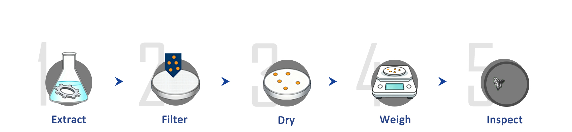




 IPv6 network supported